You have no items in your cart.
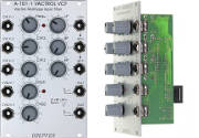

Module A152 is a very useful switching and T&H module. It combines a voltage addressed 1-to-8 multiplexer and 8 fold T&H that can be used as an analog shift register too. The active in/output is displayed by a LED. The digital output of the currently addressed step outputs “high”. The remaining digital outputs are low. Instead of voltage control even clock/reset controlled addressing of the active step is possible. The rising edge of each clock signal causes an advance to the next state. The rising edge of the reset signal resets to step 1. Basis principles: The sum of the voltages coming from the manual Address control and the CV input define the currently addressed step of the 3 sub-devices. If the module is controlled by clock and reset the control voltage has to remain unchanged as the CV control has priority over the clock/reset control (e.g. simply turn the CV control fully counterclockwise and do not touch the Address control knob). Sub-device #1 is the bidirectional 8-fold multiplexer (kind of an electronical 8-fold rotary switch). Bidirectional means that it works into both directions like a mechanical rotary switch: the common socket may work as an output that is connected to one of the 8 inputs that are e.g. connected to modulation or audio sources. But the common socket may even function as input. In this case the signal applied to the common socket is output to the currently addressed single socket. The voltage range of the in/outputs to be switched is the full A-100 voltage range -12V….+12V. All A-100 signals can be switched without any restrictions. Sub-device #2 is the addressed 8-fold T&H / analog shift register. The signal at the common T&H input is connected to the addressed T&H output. As soon as a new output is addressed the last voltage is stored at the output (Track&Hold function). The T&H section of the A-152 allows the emulation of the “toggling T&H” function of the Buchla module 266 “Source of Uncertainty”. Only the first two T&H outputs of the A-152 are required for this application. Sub-device #3 is the digital output section. The digital output of the currently addressed turns to “high”. All other digital outputs are low. The digital outputs can be used to trigger e.g. envelope generators or to control the reset input in the clocked mode to reduce the number of addressed stages. Remark: In contrast to the Sample&Hold (see S&H A-148) the output voltage follows (i.e. tracks) to the input voltage as long as the corresponding stage (1…8) is active. Just when the stage is deselected the last voltage is held. Remark: The clock signal that is fed into the Clock In socket has to be GND referenced to the A-100 frame. The reason for this is a recognition circuit at the clock input that is used to decide if the module is clock controlled or voltage controlled. For this recognition the GND pin of the Clock In socket is used. If an external clock signal is used (i.e. not coming from a module mounted into the A-100 frame where the A-152 is mounted) the GND reference is missing and the recognition circuit does not work (with the result that the clock input does not work). But there is a simple workaround: as soon as both systems are connected by means of any other patch cable that way the GND reference is established.
Technical Specs.:
- Width: 16HP
- Depth: 45mm
- Current Draw: 40mA
Related Products

Recently Viewed Products
 A-183-1 39,00 € TTC
 Bishop Miscellany 249,00 € TTC
- Brst 89,00 € TTC


