Pocket Electronic (abbreviation: “PE” in the following) is an universal electronics DIY kit to built your own MIDI control box. Up to 16 controlling elements can be connected to PE transmitting 16 different MIDI messages on different (or even the same) MIDI channels.
Essentially it contains the electronics core of Pocket Control resp. Pocket Fader but without the 16 controls (i.e. without rotary potentiometers resp. faders). Concerning the MIDI functions PE is identical to Pocket Control resp. Pocket Fader (these two devices are no longer available).
Instead of this PE is used to connect up to 16 controlling elements (e.g. rotary potentiometers, fader/slider potentiometer, touch switches, toggle switches, foot switches, foot controllers). The controlling elements are not included but have to be added by the customer. The MIDI data range is 0…127 with 7 bit resolution. The connection of the controlling elements is described in detail in the PE user’s guide.
Even voltages sources can be used instead of the controlling elements provided that the voltages applied are strictly within the range 0…+5V (referenced to PE GND) ! Voltages beyond this range will destroy the electronics ! The voltage range 0…+5V corresponds to a MIDI data range of 0…127 (7 bit resolution).
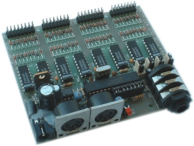
The 16 controlling elements resp. control voltages are connected to two double row pinheaders (10 pins each). To these headers two 10 pin ribbon cables are connected. The controlling elements are connected to the free ends of the ribbon cables. In this way the controlling elements can be pulled off from the electronics.
For operation a momentary switch and a LED are used. They are connected via cables to a 4 pin connector on the pc board.
The following Midi messages can be generated:
any controller, after touch, pitch bend, common RPN resp. NRPN controller, but no SysEx messages
128 presets with useful assignement of MIDI events to the 16 controlling elements (e.g. current software synthesizer, XG controller, 16 x volume on the 16 MIDI channels and so on), for nearly each application there is something ‘on board’
Selection of the desired preset after power on is adjusted with a 8 pin DIP switch
In addition the desired preset can be chosen with an incoming MIDI program change message
The free editor program (PC version) enables the user to program his own 128 presets. Sorry – a Mac version is not available.
PE is equipped with MIDI In and MIDI Out. The incoming MIDI messages are merged to the data generated by PE- provided that the incoming Midi data range is not too big.In this way several PE can be linked together to obtain larger controller arrays with more than 16 elements.
Even the combination of PE and CTM64 is possible to add controller events to the note or program change events generated by CTM64.
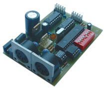
PE is available only as an assembled and tested pc board. The pc board measures are about 80 mm (length) x 56 mm (width) x 30 mm (height). Five mounting holes with 3 mm diameter are available for mounting the pc board to a suitable base e.g. with distance sleeves or spacers and screws. PE includes two 10 pin ribbon cables (about 30 cm each), button and LED (snapshot function) and within Germany even the power supply.
Doepfer do not offer a suitable housing as this would have to be completely different for various combinations of controlling elements.
An external power supply (7-15VDC@min. 100mA) is used. Within Germany the wall outlet power supply adapter for 230V mains voltage and European type mains plug is included with the PE. In other countries the power supply has to be purchased by the user in his country. If there is a Doepfer representative in your country (see dealer) please ask the representative if the power supply is included in your country.
PE is a so-called OEM or DIY product. Electronic basic knowledge is required to install the board. If you have no or only little experience with electronics we recommend not to order and not to install the PE.
We cannot take back modules or carry out warranty repairs of modules that became defective because of wrong installation or wrong connection of the controlling elements or voltages. We also cannot take back or carry out warranty repairs of modules or cables which have been soldered by the user.
The user’s manual is available as pdf file on our web site.
