Basic features
Four CV-controlled Clock Divider/Multipliers
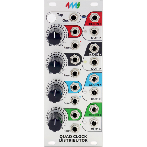
Tap tempo button and five sync’ed clock outputs make the QCD perfect for head-of-the-chain “Master” clock module
Tap clock output runs at the tapped tempo (even if other channels are being clocked externally)
Create complex rhythmic patterns by patching multiple channels into each other’s Div/Mult CV and Reset
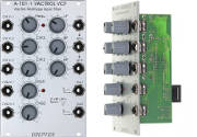
Each of the four channels has an independent clock IN, OUT, Reset and Div/Mult CV
Divide or Multiply incoming clock from /32 to x16 on each channel:
-Detented knob to snap to integer division/multiples
-CV jack to modulate Div/Mult amount
Reset jack (per channel) restarts the clock when a trigger is received (alters phase of clock)
Clock input jacks are normalized downwards: Tap->Red->Black->Blue->Green
Clock outputs stop automatically when incoming clock stops
LEDs blink to output clocks’ tempos
5V clock output pulses, fully buffered. Default is square-wave, and PW is controllable with expander
Daisy chain multiple QCDs or other clock modules using Tap Out jack
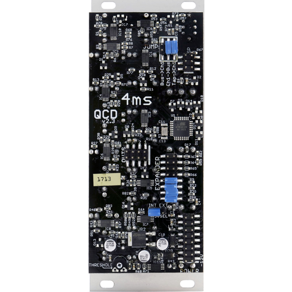
Header on the PCB to connect to Quad Pingable LFO (QPLFO) to provide four CV Skew-able, CV Div/Mult-able envelopes
Interfaces with QCD Expander for more features (Pulse Width, Inverted Gate, attenuverters for CV inputs)
Module size:
The QCD is 10HP and 1.57 inches (40mm) deep.
All pots have a metal shaft and nut.
Power consumption:
A jumper selects using +5V from the power supply, or generating +5V on-board from the +12V rail.
+12V rail:
48mA with jumper selecting external 5V
88mA with jumper selecting internal 5V.
+5V rail:
41mA with jumper selecting external 5V
not used (0mA) with jumper selecting internal 5V.
-12V rail:
40mA

