You have no items in your cart.
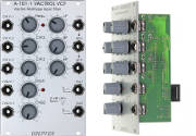

The After Later Audio Scenes is a replica of a popular multi-segment generator for Eurorack systems.
Scenes is an exact copy of the Mutable Instruments Stages. It is a function generator of a special kind. The module can be used for example as a multi-stage envelope, CV sequencer, or a combination of an ADSR envelope and two LFOs. Instead of programming fixed modes into the module, After Later Audio gives the user the ability to determine the behavior and division of the six available segments. Do you need a complex envelope or six LFOs? – With Scenes you have both in the system… and much more!
Scenes offers six segments that can be combined in any way you like. Buttons allow the selection of different modes. For editing, each segment has a potentiometer and a fader. The function varies depending on the selected mode. The same applies to the built-in CV inputs. Gate and trigger paths are used to control segments. The module automatically detects where a cable is plugged in. Accordingly, the segments are divided into groups and thus form, for example, an ADSR and an AD envelope. (Four segments for ADSR and two segments for AD.) Resulting voltage curves are available at the first output of a group. The other taps output only the voltage of the corresponding segment. Scenes generates voltages in the range 0V to +8V. If a segment is operated as an LFO, unipolar results are generated. But with a trick you can also generate oscillations in the range of -8V to +8V: Simply modulate a Hold or Step segment (see Modes) by a second segment.
The operating modes of the segments at a glance:
- Ramp: basic module for envelope and LFO edges. The segment “ramps” from one control voltage value to the next. A slider determines the time the module needs for this process. – For example, the length of the attack, decay or release phase or the LFO speed. The potentiometer and CV input determine either waveform (rising – linear – falling) or target voltage. Here it depends on how the surrounding segments are
- Step: Quasi-a sequencer step. By combining several segments you can create CV patterns. Triggers are used for further switching. Voltage values are determined by faders and CV inputs. A glide function can be adjusted with the help of potentiometers.
- Hold: Generates a fixed voltage to shape hold or sustain phases of an envelope. The CV value is determined via fader and CV input. The potentiometer determines the time value.
- In addition, there is a loop function with which one or more segments can be set to a continuous loop. – Indispensable for loop envelopes and LFO use.
- If you use a single segment in Ramp mode as an oscillating circuit, the resulting waveform can be deformed from sawtooth to triangle, sine and trapezoid to rectangle with the associated potentiometer.
Scenes can be chained to handle even more complex tasks.
| HE: | 3 |
| TE: | 14 |
| Depth: | 25 |
| Power consumption +12V: | 80 |
| Power consumption -12V: | 20 |
Related Products


Recently Viewed Products
 Spring Reverb DIY Kit 175,00 € TTC
 Stereo Line In 1U 69,00 € TTC
- Time Warp 189,00 € TTC


